February 27, 2010

Pigmented Villonodular Synovitis (PVNS) of the Ankle


Figures 1&2: Sagittal MR images in T1 (fig.1) and STIR (fig.2) show a heterogeneous para-articular mass (arrows) anterior to the ankle joint that demonstrates areas of internal low T1 and T2 signal intensity (arrowheads), consistent with hemosiderin deposits.


Facts: PVNS
  • Inflammatory synovial lesion of unknown etiology
  • Young to middle-aged adult, usually male
  • Histology shows connective tissue hyperplasia, phagocytes and hemosiderin deposition
  • Two types: localized and diffuse
  • Common involvement: knee, hip, ankle/foot
  • It is a "joint" disease that can produce mass and erode adjacent bones
  • MRI is the imaging modality of choice for suspected case of PVNS

MR Imaging Features
  • Heterogeneous para/intra-articular soft tissue mass with low T1 and T2 signal (due to hemosiderin deposition)
  • Blooming of low T2 areas in gradient echo imaging
  • Diffuse intense enhancement
  • Variable amount of joint effusion
  • Imaging mimics: rheumatoid arthritis, hemophiliac joint, amyloidosis
Reference:
Ofluoglu O. Pigmented villonodular synovitis. Orthop Clin N Am 2006;37:23-33.

Follow RiTradiology on FacebookTwitter or Google Friend Connect

February 24, 2010

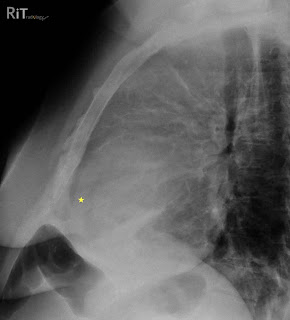
Pericardial Effusion - Oreo Cookie Sign


Figure 1: Lateral chest radiograph shows separation of the retrosternal (dark line parallel to the sternum anterior to the yellow star) and epicardial fat stripes (dark line behind the yellow star). This patient also has an anterior mediastinal mass due to lymphoma.
Figure 2: Axial contrast-enhanced CT image shows a large pericardial effusion (stars) separating the retrosternal fat stripe (double-headed arrow) and epicardial fat stripe (arrowheads).


Facts: Pericardium
  • Pericardium has two layers: visceral (attached to myocardial surface and proximal great vessels) and parietal (free wall of pericardial sac)
  • Pericardial sac normally contains 20-50 mL of fluid
Facts: Pericardial Effusion
  • Most common cause = myocardial infarction with left heart failure
  • Other causes: uremia, hypoalbuminemia, myxedema, infection, drug reaction, trauma, neoplasm, autoimmune disease
  • Can be seen on radiography if volume exceeds 250 mL
Imaging Features
  • PA or AP radiograph: water bottle-shaped morphology of the cardiomediastinal shadow
  • Lateral view: separation of retrosternal and epicardial fat stripes by more than 2 mm (Oreo cookie sign)
  • Oreo cookie sign: epicardial fat and retrosternal fat stripes = outer dark cookie layers; opaque fluid = white fluff of the cookie

Reference:

Parker MS, Chasen MH, Paul N. Radiologic signs in thoracic imaging: case-based review and self-assessment module. AJR 2009;192:S34-S48.


Follow RiTradiology on Facebook, Twitter or Google Friend Connect
Visit RiT Illuminations to view nice pictures of your colleague

February 21, 2010

Lipid Poor Adrenal Adenoma

Facts
  • Most adenomas can be characterized as lipid rich on precontrast scan, which will show attenuation value of less than 10 HU
  • Some adenomas are lipid poor, therefore demonstrate a higher attenuation value. This can be further characterized by performing an adrenal mass CT protocol
  • Adrenal mass CT consists of 1) precontrast, 2) portovenous phase postcontrast (60-70 sec) and 3) delayed phase (10-15 min)
  • Measurement of region of interests (ROI) over > half of the mass at different phases. Values are used to calculate absolute and relative percentage washout

Absolute Percentage Washout (APW) = 100 x (portovenous attenuation - delayed attenuation)/(delayed attenuation - precontrast attenuation)

Relative Percentage Washout (RPW) = 100 x (portovenous attenuation - delayed attenuation)/delayed attenuation

Adenomas typically show rapid washout
  • APW > 60% OR
  • RPW > 40%
Reference:

Johnson PT, Horton KM, Fishman EK. Adrenal imaging with multidetector CT: evidence-based protocol optimization and interpretative practice. RadioGraphics 2009;29:1319-1331.

February 18, 2010

Multiple Well-Defined Soft-Tissue Opacities in the Breasts

Mediolateral oblique mammogram of both breasts show multiple, innumerable, well-defined soft-tissue opacities (arrows) and enlarged nipples in a 40-year-old woman.


Differential Diagnosis
  • Cysts
  • Fibroadenomas: 10-20% are multiple
  • Skin lesions: such as neurofibromas
  • Intramammary lymph nodes
  • Metastasis: melanoma (most common), lymphoma (2nd most common), lung, ovary, soft tissue sarcoma (breast metastasis has a very poor prognosis)
Our case: neurofibromatosis

Reference:
Davies SG. Chapman & Nakielny's Aids to radiological differential diagnosis, fifth edition, 2009.

February 15, 2010

Left Inferior Vena Cava (IVC)


Axial contrast-enhanced CT images show the left IVC (arrows) crossing the midline from left to right of the aorta, joining the left renal vein that units with the right renal vein to be a normal right sided suprarenal IVC. Image at the lower section shows the IVC located to the left of the aorta. Without scrutinization, this anomaly can be misdiagnosed as left paraaortic adenopathy.


Facts: IVC Anomalies
  • As many as 14 forms of IVC anomalies are theoretically possible
  • More than one anomaly can coexist in a patient, for example, double IVC + retroaortic right renal vein + hemiazygos continuation
  • Common anomalies are circumaortic left renal vein, retroaortic left renal vein, left IVC, double IVC, azygos continuation of IVC

Left IVC
  • Regression of the right supracardinal vein with persistence of the left supracardinal vein
  • Prevalence 0.2% - 0.5%
  • Left IVC joins the left renal vein, which crosses anterior to the aorta and units with the right renal vein to form a normal right sided suprarenal IVC.
  • Clinical significance: potential for misdiagnosis as left paraaortic adenopathy, difficulty placement of IVC filter
Reference:
Bass JE, Redwine MD, Kramer LA, et al. Spectrum of congenital anomalies of the inferior vena cava: cross-sectional imaging findings. RadioGraphics 2000;20:639-652.

February 12, 2010

Insidious Hypersensitivity Pneumonitis

Axial CT image shows bilateral numerous centrilobular groundglass opacities (arrows) and areas of air trapping (heterogeneous low attenuation in lung parenchyma) in this 57-year-old nonsmoker.


Facts: Hypersensitivity Pneumonitis
  • Numerous etiology: exposure to microbes, animal protein, plant protein, low-molecular-weight chemicals
  • Clinical features depend on the amount of allergen, duration of exposure, nature of antigen and host factors
  • Clinical syndromes divided into three types: 1. acute (or episodic) with improvement between attacks, 2. insidious with superimposed acute attack, 3. insidious without acute attacks
  • Histology shows cellular bronchiolitis, diffuse chronic interstitial infiltrates, nonnecrotizing granulomas or giant cells in alveoli/interstitium
  • Much more common in nonsmokers
Imaging Appearance
  • Usually not seen on chest radiograph. Bilateral groundglass opacities and fine reticulations can be seen (similar appearance to pulmonary edema). If fibrosis occurs, reticular opacities and honeycombing is visualized
  • On CT: centrilobular ground glass opacities (less than 5 mm ill-defined nodules in centrilobular distribution), air trapping and diffuse groundglass opacities
  • Usually symmetric in the mid/lower lungs
Diagnosis
  • Clinical history + lab test (Antibody testing) + bronchoalveolar lavage finding + imaging
  • In BAL, there is increased lymphocytes with CD4:CD8 ratio of less than 1

Our case: insidious hypersensitivity pneumonitis due to unknown etiology, the diagnosis was confirmed with BAL and lung biopsy. The main differential diagnosis based on imaging in this case was NSIP.

Reference:
Hirschmann JV, Pipavath SNJ, Godwin JD. Hypersensitivity pneumonitis: a historical, clinical and radiologic review. RadioGraphics 2009;29:1921-1938.

February 9, 2010

Spinal Fracture in Ankylosing Spondylitis

Sagittal-reformatted CT image of a patient with known ankylosing spondylitis shows a through-and-through fracture involving the ossified syndesmophyte and the body of C7 to its posterior cortex.


Facts: Ankylosing Spondylitis (AS)
  • Rheumatologic condition with progressive ossification of spinal ligaments and ankylosis of facet joints leading to total stiffness
  • Patients with AS often have osteoporosis as a result of chronic inflammation, disuse and from the use of steroid medication; therefore they are at risk of developing fracture.
  • Minor trauma (or even no trauma) can result in fractures of ankylosed spine
Facts: Fractures in Ankylosing Spondylitis
  • Different pattern than in a normal spine
  • Fracture line goes entirely through bone, either through vertebral body, ossified ligaments or both
  • Fracture can "open up" in flexion or extension
  • Can be complicated by epidural bleeding, secondary displacement (either hyperflexion or hyperextension), loss of fixation and increased mortality

Reference:
Olerud C, Frost A, Bring J. Spinal fractures in patients with ankylosing spondylitis. Eur Spine J 1996;5:51-55.

February 6, 2010

Calcific Tendinitis of the Longus Colli

Sagittal-reformatted CT image shows calcification in the soft tissue anterior to C2 (arrow) and adjacent soft tissue swelling (arrowhead) in a patient presenting with acute non-traumatic neck pain.

Facts: Longus Colli
  • Longus colli muscles, along with longus capitis are bilateral paired neck flexor that make up the prevertebral space.
  • The superiormost fibers of the longus colli attach to the anterior tubercles of C1.
  • See the anatomy of longus colli muscle
Facts: Calcific Tendinitis of Longus Colli
  • Inflammatory condition due to deposition of calcium hydroxyapatite in the superior tendon fibers of the longus colli
  • Uncommon disease, mostly seen between 30-60 years old
  • Radiography and CT shows calcific (nonosseous) density in the prevertebral/retropharyngeal soft tissue anterior to C1-C2 WITH associated soft tissue swelling
  • There may be fluid/effusion in the retropharyngeal space that can appear quite extensive
  • Differentiation from retropharyngeal abscess/infection is important. In this disease, the fluid smoothly expands the retropharyngeal space, no enhancing wall, no associated suppurative lymph nodes and there is presence of calcification of the longus colli tendons.
Reference:
Eastwood JD, Hudgins PA, Malone D. Retropharyngeal effusion in acute calcific prevertebral tendinitis: diagnosis with CT and MR imaging. AJNR Am J Neuroradiol 1998;19:1789-1792.

Follow RiTradiology on Facebook, Twitter or Google Friend Connect
Visit RiT Illuminations to view nice pictures from your colleague

February 3, 2010

Radiation Exposure from CT, PET/CT Will Be Tracked at the NIH


Current Issues & Debates
  • Controversies exist whether low-dose (less than 150 mSv) medical radiation tests are related to development of cancer.
  • Model used to extrapolate the cancer risk from low-dose medical radiation exposure is a "linear-no-threshold hypothesis", which implies that any amount of ionizing radiation (even small) has a finite probability of inducing cancer.
  • This approach is widely accepted and used for radiation protection regulations and guidelines by the International Commission on Radiological Protection.
  • Several recent studies and news reports have raised concerns regarding radiation exposure from medical devices (particularly CT and nuclear cardiology)
  • A recent study published in the Archives of Internal Medicine estimated that radiation from CT might cause 29,000 new cancers and 14,500 deaths a year. Another study in the same journal pointed out that patients may have received much higher radiation from imaging tests than previous believed. Read synopsis in the older RiT post.
Addressing These Issues by NIH
  • Radiology and Imaging Sciences at the National Institutes of Health (NIH) Clinical Center will incorporate radiation dose exposure reports into the electronic medical record (EMR)
  • The process will be developed in corporation with major equipment vendors beginning with exposures from CT and PET/CT
  • Radiation dose will be recorded, entered into DICOM header for CT and PET/CT and stored either in radiology information system or preferably hospital-based EMR. It should be trackable by patients in their own personal health records
What Will It Do?
  • It is the first step toward monitoring patient dose
  • It is the basis for future research on this subject
  • Who knows, in the future this may be required in all institutions...
Are you monitoring patient dose of CT and PET/CT in your institution? If yes, how?

Reference:
Neumann RD, Bluemke DA. Tracking radiation exposure from diagnostic imaging devices at the NIH. J Am Coll Radiol 2010;7:87-89.

ShareThis